

A roof plan showing four slope arrows and two drain symbols is not ready to build. The pass-or-revise question is whether water can follow two measurable paths from every finished roof surface: one primary drainage path and one independent emergency path. A low-slope roof is a two-path hydraulic system, not a flat architectural shape.
Does the low-slope roof plan for this modern house design pass a drainage audit?
A low-slope roof plan for a modern house design passes only when every roof zone has a defined primary outlet, positive fall at the finished membrane, code-sized drainage components, and an independent overflow route where required. Each item must be checked against local codes, project rainfall data, structural assumptions, roof geometry, and the selected roofing system.
Drain symbols and slope arrows do not prove drainage. Before approving the architectural design, assemble the project address, governing authority, permit date, and locally adopted residential or building code and plumbing code, including amendments. The IAPMO Uniform Plumbing Code reference identifies both 2021 and 2024 editions, which is why the drawings must name the edition actually adopted for the project.
The audit also needs the specified membrane system and a dimensioned roof plan showing parapets, ridges, valleys, roof steps, drains, scuppers, gutters, equipment, curbs, expansion joints, access points, and door thresholds. Stock plans rarely settle these location-specific inputs, so include roof drainage among the architectural checks to complete before buying house plans.
- Define the geometry. Record finished membrane elevations at high points, valleys, sumps, outlet flanges, thresholds, and parapet openings.
- Assign primary capacity. Give each outlet a tributary area, rainfall input, rated capacity at the design head, pipe or scupper size, and discharge destination.
- Assign secondary capacity. Provide an independent emergency route where required, with its inlet elevation, capacity, and termination stated.
- Coordinate structural rain load. Reconcile blocked-primary water depth, overflow elevation, roof deflection, and ponding review with the structural design.
- Complete the assembly details. Coordinate membrane, insulation, drain sump, flashing, attachment, curb, and roof-edge construction.
- Make overflow observable. Route emergency discharge where occupants or maintenance staff can see water and investigate the blockage.
Each enclosed roof zone needs a named primary and secondary discharge path
A roof-zone schedule should give every hydraulically separate basin a unique identifier and measured area. Parapets, curbs, expansion joints, and roof steps can divide one drawn roof into several basins, including shallow pockets without a useful outlet.
For each zone, schedule the primary outlet, secondary outlet, design rainfall input, and final discharge point. Flow arrows and outlet labels must match the architectural plan, plumbing risers, and drain schedule. “Drain by plumber” is not a defined path, and an unlabeled scupper does not establish where water goes. The schedule should also state whether emergency discharge is visible from an occupied area or routinely inspected location.
The roof audit must distinguish code minimums from manufacturer warranty conditions
Code acceptance does not establish roof-system acceptance. Record applicable provisions for slope, primary drainage, secondary drainage, and rain-load design separately from the selected membrane manufacturer’s requirements for minimum slope, ponding water, sumps, flashing, attachment, maintenance, and warranty coverage.
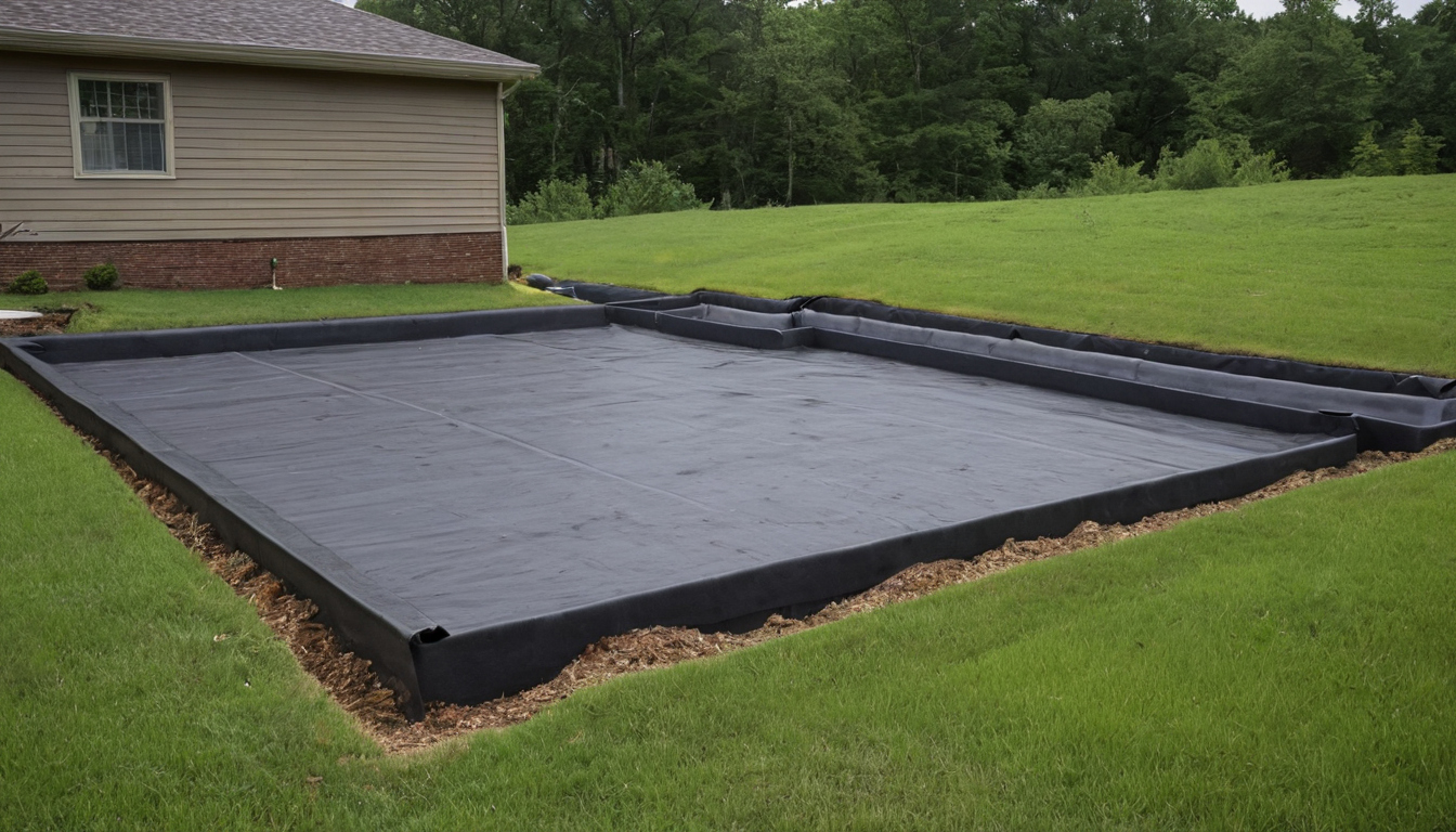
Does the low-slope roof plan for this modern house design pass a drainage audit shown with practical context cues.
Where the code, manufacturer, insurer, or owner sets different criteria, the construction documents should identify the controlling requirement rather than leaving the installer to choose. The next test is more exacting: positive drainage must be demonstrated at the finished roof membrane because structural deck arrows cannot show the final water path.
Positive drainage must be demonstrated at the finished roof membrane
Low-slope residential architecture must show fall at the finished membrane, not merely place slope arrows on the structural deck. The calculation must account for framing elevations, anticipated deflection, insulation build-up, drain sumps, crickets, curbs, construction tolerances, the locally adopted code, and the selected membrane manufacturer’s requirements.
How should roof slope be calculated from rise, run, and finished elevations?
Calculate slope as rise divided by horizontal run and record the result consistently as inches per foot, a ratio, or a percentage. For a hypothetical 24-foot flow path designed at 1/4 inch per foot, the required elevation difference is 6 inches. The equivalent slope is 1:48, or about 2.08 percent.
- Dimension the high point, drain flange, sump bottom, valley, and perimeter elevations.
- Show structural deck slope, tapered-insulation slope, and resulting finished-membrane slope separately.
- Check the longest water path and shallowest valley, not only the main roof plane.
- Coordinate framing direction, calculated deflection, long-term movement assumptions, and identified ponding risks with the structural engineer.
- Use one elevation datum and drawing precision suitable for fabrication. Do not conceal a calculated shortfall by rounding upward.
Questions about a plumbing-code provision can be directed to the code publisher. IAPMO states that it provides code answers, analysis, and interpretations through its request service at 1-800-201-0335. That assistance does not replace a project determination from the authority having jurisdiction.
A roof cricket must preserve positive fall along both sides and through the valley
A cricket passes when its ridge elevation, base width, length, side slopes, valley slopes, and receiving outlet elevation form an uninterrupted descending route. A raised drain flange or a shallow valley behind a curb can defeat an otherwise adequate main-roof slope.
Plot flow around chimneys, wide curbs, equipment, roof-access curbs, and spaces between drains. Cricket discharge must not terminate at a wall, dead valley, or higher membrane surface. The detail must also follow the membrane manufacturer’s requirements for saddles, reinforced corners, flashing transitions, and bends.
Tapered-insulation shop drawings must reconcile every drain, cricket, and perimeter elevation
The submittal should identify base thickness, taper rate, cricket taper, layer count, panel layout, cover board, drain-receiver depth, sump geometry, and total assembly thickness. Spot elevations belong at drains, valleys, ridges, scuppers, curbs, crickets, and parapets.
Attachment or adhesive patterns must match the approved roof assembly and project wind design. Conflicts among shop drawings, structural elevations, plumbing outlets, and specified roof heights require a coordinated revision before insulation fabrication. Once the geometry passes, outlet capacity must be checked against rainfall and tributary area.
Roof drains, scuppers, gutters, and leaders must be sized from rainfall and tributary area
Primary roof drainage cannot be selected by outlet diameter alone. Sizing starts with the rainfall intensity prescribed by the locally adopted code, followed by the tributary area reaching each outlet and approved product-capacity data under the stated hydraulic head and installation conditions.
How is the tributary area assigned to each roof outlet?
A scaled drainage-basin diagram should assign square footage to every outlet. Basin boundaries must follow finished ridges, crickets, curbs, expansion joints, roof steps, and valleys rather than convenient plan divisions. No basin should depend on water crossing a ridge, raised curb, or reversed-slope joint. Where the adopted code requires adjacent vertical surfaces to contribute area, the calculation should show that adjustment.
The calculation record should identify the prescribed rainfall source, storm duration, recurrence interval, and project-site rainfall value. It should also state assumptions for transfer between connected basins and multiple drains feeding a common horizontal conductor. IAPMO identifies the Uniform Plumbing Code as a code used by many municipalities, but that does not establish the edition or local amendments governing a particular address.
The roof drainage schedule should record capacity, head, pipe size, and discharge point
The schedule should list outlet identification, basin area, rainfall rate, required flow, selected assembly, rated capacity, design head, outlet size, leader size, and final discharge destination. Hydraulic head is the water depth above the inlet at which the product capacity is rated. For piping, record material, slope, developed length, fittings, offsets, cleanouts, transitions, and cumulative load where drains join one conductor.
Drain entries should identify the body, clamping ring, strainer, extension, under-deck clamp, sump receiver, and membrane compatibility. Scupper entries should identify opening width and height, sill elevation, throat length, conductor head, downspout, and relationship to the overflow. Coordinate each discharge with site stormwater disposal, splash control, walks, and property lines.
A primary system can pass its capacity calculation and still fail during a blockage. The next check is whether emergency drainage remains independent, visible, and within the structure’s reviewed rain-load depth.
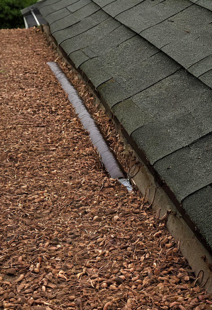
Roof drains, scuppers, gutters, and leaders must be sized from rainfall and tributary area shown with practical context cues.
An emergency overflow path must remain independent, visible, and structurally safe
Where parapets or other construction can retain water, the roof needs the secondary drainage required by the locally adopted code. The secondary inlet, capacity, piping, and discharge cannot depend on the same blocked component as the primary system. The resulting water depth must remain within the structural rain-load design.
Overflow inlet elevations must coordinate with structural rain-load assumptions
The roof plan, plumbing drawings, and structural calculations should place the roof low point, primary inlet, overflow inlet, parapet top, doors, flashings, and wall openings on one elevation datum. The overflow elevation establishes how much water can accumulate before emergency drainage begins, but it does not establish the maximum water surface.
A secondary device needs hydraulic head above its inlet to reach its rated capacity. The designer must add that operating head to the elevation difference between the roof low point and overflow inlet, then compare the calculated water surface with the structural engineer’s design water depth and every vulnerable opening. A shallow scupper may begin flowing yet remain below its scheduled capacity.
The structural engineer should confirm the adopted rain-load criteria, blocked-primary assumption, roof deflection, design water depth, and ponding-instability review. The architectural design must not raise an overflow scupper for façade alignment after those calculations are complete. A parapet also cannot be treated as reserve water depth unless the structure, flashings, and openings were designed for the retained water.
Emergency roof drainage should discharge where blockage becomes observable
The secondary route should remain separate from the obstructed primary component and terminate as required by the adopted code and authority having jurisdiction. If local rules permit shared downstream piping, the design still needs proof that the shared portion cannot defeat both paths. A concealed connection that masks emergency flow also removes the warning that the primary system needs service.
Exterior elevations should show each overflow termination and discharge direction. A conspicuous outlet may leave a visible stream or stain on an exterior wall, but visibility cannot create another hazard. Keep discharge away from entrance doors, pedestrian walks, electrical equipment, erodible soil, neighboring property, and locations where freezing water could form ice.
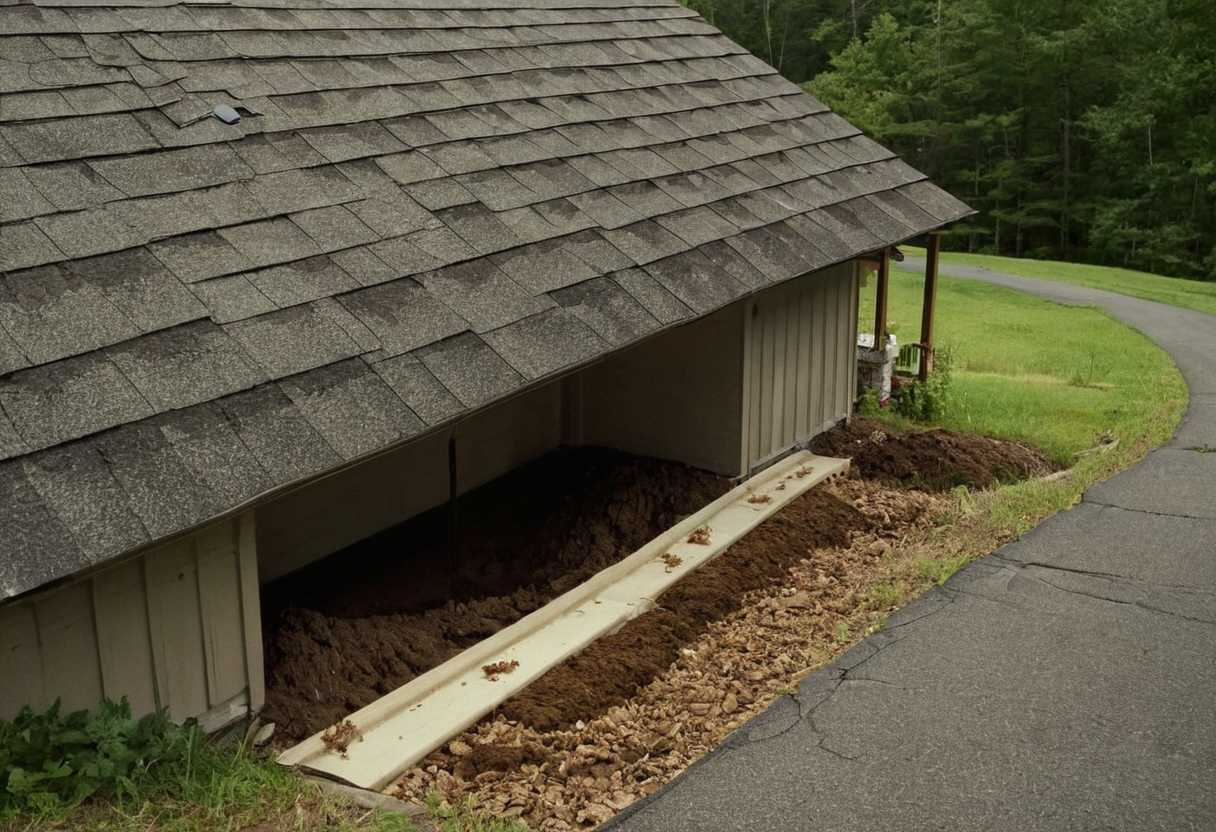
An emergency overflow path must remain independent, visible, and structurally safe shown with practical context cues.
The owner’s maintenance plan should state that overflow discharge means the primary drain, scupper, leader, or outlet requires prompt inspection. Once both paths pass review, the documents must convert the design into purchasable roofing and drainage scope.
The construction documents must convert roof drainage design into purchasable scope
A buildable home architecture design must place drainage requirements in coordinated drawings, schedules, specifications, and bid scope. Every outlet and tapered-insulation zone needs a quantity, location, dimension, finished elevation, material, accessory set, and assigned trade responsibility.
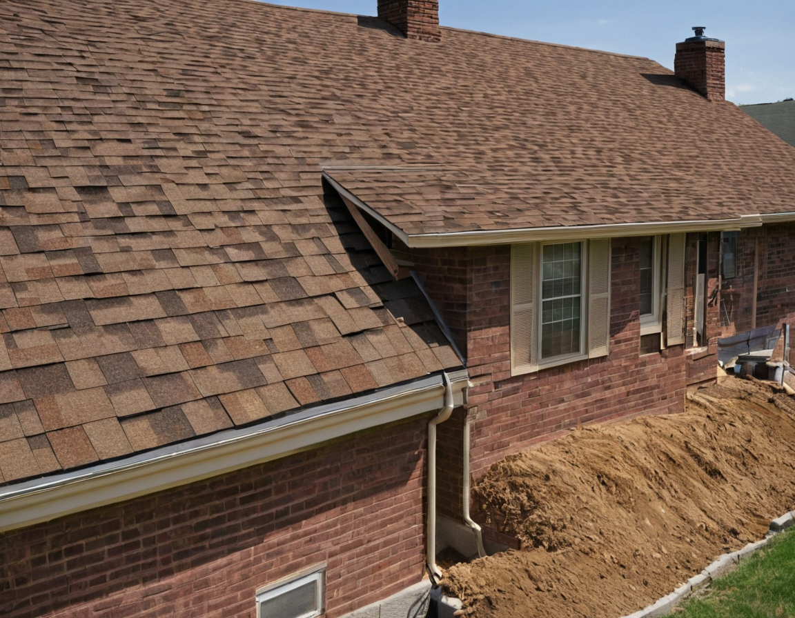
The construction documents must convert roof drainage design into purchasable scope shown as an editorial planning reference.
What belongs in the roof drainage specification and purchase order?
The permit and bid set should coordinate the roof plan, drain and scupper details, building sections, exterior elevations, plumbing risers, structural notes, and drainage schedules. A responsibility matrix should assign design and submittal review among the architect, structural engineer, plumbing designer, roofing manufacturer, roofing contractor, and tapered-insulation supplier. This coordination belongs within matching the design professional’s scope to the project.
- List the product, quantity, roof zone, outlet dimensions, material, finish, strainer, flange, connection, and membrane interface.
- Count drains, scuppers, conductor heads, downspouts, sumps, tapered insulation, crickets, cover board, and flashing accessories.
- Assign blocking, sleeves, penetrations, piping, sealants, temporary protection, fasteners, and sheet metal.
- Require shop drawings, calculations, assembly approvals, warranty confirmation, installer qualifications, and closeout documents.
Building materials and coatings can release volatile organic compounds. The U.S. Environmental Protection Agency identifies building materials, paints, varnishes, waxes, cleaning products, and furnishings as common indoor VOC sources and recommends increased ventilation when emitting products are used indoors. Specifications should address ventilation if roofing sealants, coatings, or cleaning products are applied near occupied interiors or air intakes.
Roof drainage substitutions require a new geometry and capacity review
An “equal” outlet is not equal if its flange sits higher, its strainer restricts flow, or its connection changes the sump. Compare proposed and specified capacity at equal hydraulic head, then check flange elevation, sump dimensions, membrane compatibility, insulation thickness, attachment, and roof-system approval. Obtain revised shop drawings and written acceptance before purchase. Installed-cost comparisons require current regional material and labor quotations.
Field acceptance must verify elevations, unobstructed flow, and safe testing before concealment
The installed roof should be accepted from measured conditions, not appearance alone. Before membrane completion and again at closeout, verify deck and outlet elevations, tapered-insulation layout, cricket geometry, drain clamping, overflow separation, and visible discharge.
A roof drainage inspection should occur before insulation and membrane hide the controlling elevations
The architect, roofing consultant, or designated contractor should record deck, drain, scupper, curb, and parapet elevations with a laser level before roofing starts. The approved tapered-insulation shop drawing should remain available during insulation placement, before sumps and outlets are concealed, and at final completion.
Raised drain flanges, low deck areas, altered crickets, framing conflicts, and misplaced overflow penetrations require correction or written approval. Field changes that alter drainage basins or outlet elevations also require revised record drawings.
Drainage testing must not create an unreviewed roof load
No drain should be plugged for intentional impoundment until the structural engineer approves the water depth and load. The roofing manufacturer and authority having jurisdiction should also approve the test method, duration, weather limits, monitoring, and means of immediate drainage. Testing must preserve emergency protection rather than disabling both paths.
Closeout records should document leakage, flow direction, residual ponding, outlet operation, and corrective work. Photographs should show primary and secondary outlets, concealed piping where permitted, and visible terminations. Accept the roof only when both hydraulic paths are measurable, unobstructed, and observable.
Frequently asked questions
What is the minimum slope for drainage on a low-slope residential roof?
There is no project-independent answer. Use the locally adopted code and the selected roof-system manufacturer’s published requirements, then demonstrate the resulting slope at the finished membrane. A nominal design slope does not excuse a raised drain flange, reversed valley, or deflected low point.
What slope should a roof cricket have behind a curb, chimney, or parapet?
The cricket must create positive fall along both sides and through its receiving valley. Specify ridge, valley, base, and outlet elevations rather than relying on a generic triangle. The required geometry depends on the obstruction width, main-roof slope, flow direction, membrane details, and available assembly thickness.
How are roof drains and scuppers sized for local rainfall and tributary area?
Start with the rainfall input required by the adopted plumbing code. Assign each outlet a finished-roof tributary area, calculate required flow, and select components from capacity data at the stated hydraulic head. Confirm downstream leader and conductor capacity as connected loads accumulate.
When does a low-slope residential roof require a secondary drain or overflow scupper?
Apply the locally adopted code to the specific roof enclosure and drainage arrangement. Roof areas where parapets or other construction can retain water commonly require secondary drainage. The overflow elevation and operating head must also agree with the structural rain-load calculation.
What is the roofing “25 rule,” and does it establish any universal requirement for roof slope or drainage?
The phrase is not a universal code provision and may refer to different trade practices in different contexts. Do not place it in a specification without identifying an applicable code section, manufacturer instruction, or contract definition. Approve the roof from stated elevations, rainfall calculations, product capacities, and two complete discharge paths.